![]()
|
|
|
|
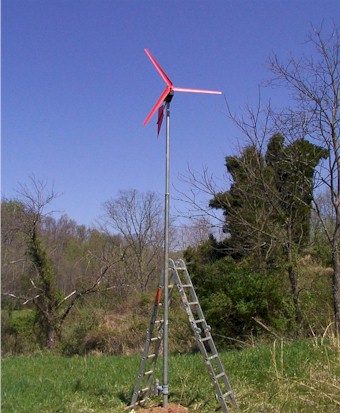
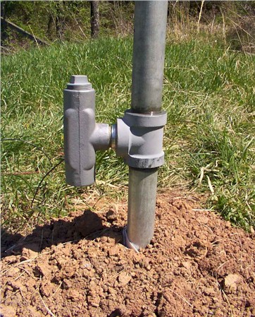
Fischer Technical Services (Ametek 30) Getting it setup Testing with a battery Close-up view of the slip joint for joining two different sizes
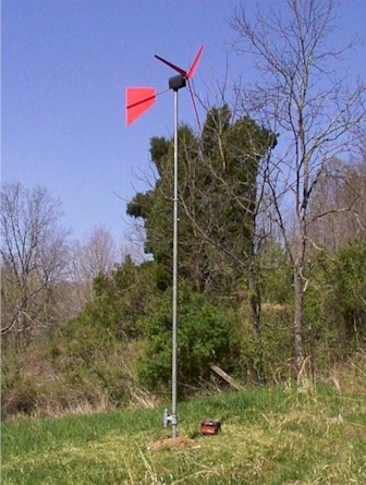
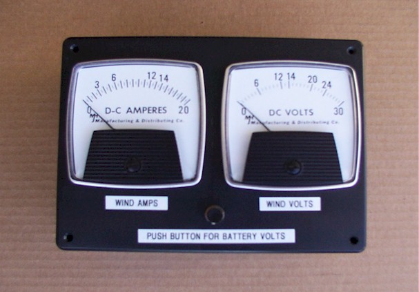
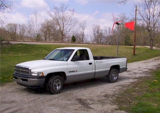
of pipe. Wiring Tee for the wires to exit the inside of the pole. Yaw mount Another view Rear view Front View Power monitoring system A view of the setup as it was being tested before the actual
install. Information supplied by Fischer Technical Services for this setup. The I-beam has a hole drilled which just provides clearance for a 2-1/2 inch long, 1/2 inch NPT, schedule 40 pipe nipple. The nipple has a coupling on each end. The top side of the top coupling is fitted with a cord grip. The bottom side of the lower coupling has another short pipe nipple to aid in assembling the "bearing." There is a 7/8" flat washer between the top coupling and the I-beam. The lower end of the 2-1/2" nipple passes through a 1-1/2 inch pipe end cap and is held in place by the lower coupling. Two Teflon washers were cut from a piece if flat material and are stacked between the I-beam and pipe to provide a low friction bearing surface. Wires from the generator run down through the pipe nipple bearing since there are reports on the internet that the winds tend to blow generators both directions more or less equally and wires do not need to be untangled very often. If twisting becomes a problem, I will make changes then. Updated 5-7-06 I built the generator with an electronic 2-stage braking system installed but it produced some objectionable electrical switching noise and I jumped it out. The electronics first loaded the generator with resistors then switched a set of relay contacts across the generator output if voltage continued to increase. The wires running down through the pipe have not twisted apart. I will check on them again in the early spring. The generator is still up and functioning. I hope you are doing well and the posting of my pictures looks good. Generator Construction
The hub is fastened to the shaft
arbor with double nuts to prevent loosening with vibration.
The motor is mounted to a 1/8”
plate welded to an 18” length of 4” steel I-beam. The I-beam
section is light weight and has a hole drilled which just
provides clearance for a 2-1/2 inch long 1/2 inch NPT schedule
40 pipe nipple.
There is also a
plastic/rubberized seal around the shaft, between the mounting
plate and the propeller hub. It was made from a suction cup
hanger drilled just large enough for shaft clearance and held in
place with silicone. There is a hole drilled in the lower
quadrant of the suction cup. Any water that gets in should run
out the hole before it gets high enough to reach the motor
shaft. Generator Performance This generator was built to keep a 12 Volt, lead-acid battery charged. The battery provides power for a 2-way radio, AM-FM radio and cell phones at a remote hunting camp that has no commercial power. The power demand is intermittent with most use in November and December.
The wind generator output could
be connected directly to the battery but it has enough over
voltage potential to damage not only the lead-acid battery but
any sensitive electronics connected to the battery. I considered adding dynamic braking but decided against it due to the fact that wind gusts of more than 40 mph are rare at the generator site. The power developed by the generator is proportional to rotor speed. There is some performance data for Ametek motors used as generators at TLG Windpower but most of it shows output as a function of propeller RPMs. I could not find any information on the PM motor I was using for this project. In addition, I was more interested in performance as a function of wind speed so I mounted the generator to the pickup and collected some data while driving down the road. Unfortunately, there was intermittent wind of approximately 5 to 6 mph on the day I was running the test. I had to make several runs, in different directions, then average the results. To summarize what I found: the generator will develop about 18 Volts in 15 mph wind with no load and about 13 Volts in 15 mph wind with a load of 1.7 Amps. I was not charging a battery during these tests since the output would depend on the charge of the battery. The generator output was connected to a 7 Ohm load resistor. As near as I could tell, the generator will deliver a little under 1 Volt/mph wind after the generator started turning. Five to six mph wind was required to start the turbine. Let me say, again, these are approximate numbers that I averaged from several runs up and down the road. I recorded widely variable output results with the truck moving at the same speed. I was satisfied that the unit would charge a battery and proceeded to install it at the camp.
Notes: |